
12 Jun Crack growth simulation of a pressure vessel opening
The International Committee on Aeronautical Fatigue and Structural Integrity (ICAF) was formed in 1951 in response to the growing concerns regarding fatigue problems in aircraft structures. The ICAF 2019 conference has been hosted in Krakow, Poland, and during the conference René Alderliesten gave the Dutch National Review (title: Review of aeronautical fatigue and structural integrity investigations in the Netherlands during the period March 2017 – March 2019).
One of the topics covered during the Dutch national review was the work of Jan Waleson from GKN Fokker: “Analysis of weight reduction of Al-Li high-altitude fuselage”. 4RealSim was mainly responsible for the Finite Element simulations in this project.
Lighter Al-Li design with integrated doubler and bonded stringers
GKN Fokker manufactures bonded fuselage skin panels. Materials applied are 2024-T3 Clad for skins, 7075-T6 Clad for doublers and triplers, 7075-T73511 extrusions for stringers. The feasibility of a lighter Al-Li design with integrated doubler and bonded stringers was investigated for the skin panels. Both 2060-T8E30, which performs well for damage tolerance, and the more balanced 2198-T851 were analysed. Further, a comparison with 2425-T3 Clad was made. Because the thickness of the skin pockets is likely to have the largest effect on weight, the study focused on the criterion that was sizing for this thickness. Analysis showed that the general buckling (Johnson-Euler) level was not critical for the skin pocket thickness and that the level could be increased by adding relatively little weight to only the bulb of the stringer in these panels, see Figure 1.
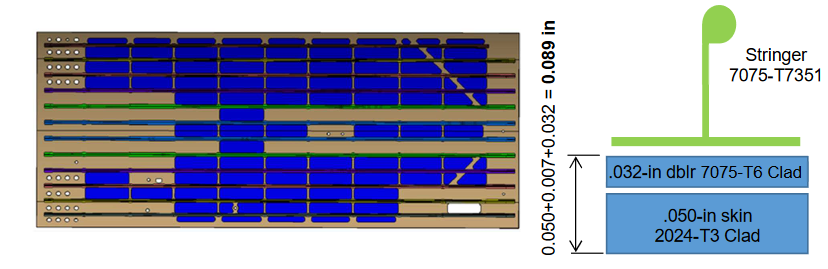
Figure 1 Left: Fuselage panel with bulbed stringer section, right: cross section through stringer location.
Maximum pressure vessel opening for longitudinal cracks
In large areas of high altitude fuselages (altitudes above 45,000 ft) the sizing criterion was found to be the maximum acceptable cabin pressure loss or maximum pressure vessel opening for longitudinal cracks (with broken frame) after the required crack growth period [1].
The comparative analyses of the pressure vessel opening were limited to a mid-bay crack in .045-in skin pockets made of the new materials, because this type of analysis could be correlated with available test results for the .050-in 2024-T3 Clad baseline. It was assumed that a skin option which performance was sufficient for a mid-bay crack would also be feasible for a crack with broken frame.
Da/dN data for the new considered alloys were only available at R=.1. Therefore, an equivalent number of cycles at equal ∆K, but with R=.1 was computed for the crack length and pressure vessel opening in .050-in 2024-T3 Clad, with which the number of cycles of the new alloys could be directly compared. Any different effect of the R-ratio on the alternative skin materials had to be neglected due to lack of data.
Analysis of pressure vessel opening
The pressure vessel opening of a mid-bay crack after growth during 4 intervals from a clearly detectable crack was used to compare the skin alloys. Both the crack growth rate and bending stiffness have an effect on the opening, which both were included in the analysis. To take advantage of better crack growth behaviour of the new alloys and the higher stiffness of the Al-Li alloys they were analysed with a smaller skin pocket thickness: .045 in compared to .050 in of the baseline 2024-T3 Clad.
The smaller thickness increases the normal stress, which has an effect on the rate and, hence, the length of the crack and the pressure vessel opening. Cracks that initiate along stringers tend to grow away from the stringer, which causes flapping of the skin, see Figure 2. The smaller thickness decreases the bending stiffness limiting the flapping, which also has a direct effect on the pressure vessel opening.
Before using the analysis for the assessment of the new alloys, it was validated with a test on a curved pressurized panel for the baseline material 2024-T3 Clad of .05-in thickness.
Figure 2: The FEM result that reproduces the crack along a stringer growing away from it and causing flapping of the skin.
The adopted XFEM analysis approach was developed by 4RealSim in Abaqus. In the area of the crack the skin is split in three layers of quadratic hex-elements:
• Outer layers of .0039 in (.10 mm) thick;
• Middle layer of .0421 in (1.07 mm) thick.
The crack tip is assumed one straight line through all layers, normal to the surface. A contour integral J on either side of the skin was computed in a geometrically non-linear ABAQUS Standard analysis, see Figure 3. The maximum J of both Jinner surface and Jouter surface was selected to compute the rate and crack angle. Assuming J equal to the strain energy release rate G, an equivalent mode-I stress intensity factor Keq is calculated as a function of the crack length using:

assuming a pure plane stress state for the .045 and .050-in skins. Note that for plane strain the resulting Keq is a factor 1/(1-ν2) higher.
Further, the crack angle as function of its length was determined as the angle of the crack extension that yielded the largest difference in J (or strain energy). For the .045-in Al-Li and .050-in 2024-T3 Clad skin pockets different models were created to account for the effect of the stiffness on the stress distribution, the crack angle, and the bending. Note that the models depend on the stiffness of the material but were assumed independent of the da/dN curve. With this curve the growth rate was calculated using Keq, from which the crack length as function of the number of cycles was determined.
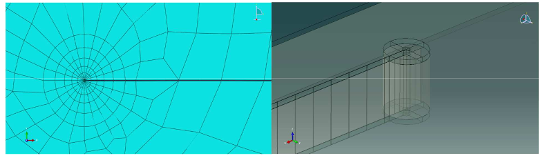
Figure 3: Meshing to compute contour integral J on either side of the skin.
Correlation of .050-in 2024-T3 Clad analysis with test
Input data and analyses with an effect on the final computation of the pressure vessel opening are:
• Far field stress distribution including skin pillowing, which was correlated to test;
• Computation of the J-integral including the effect of skin bending;
• Derivation of the equivalent mode-I ∆K;
• Da/dN data;
• Computation of the crack angle;
• Local bending of local crack edges.
Figure 4 shows the correlation of the crack length of the analysis with that of the test for .050-in 2024-T3 Clad at 11 psi pressure differential cycles (R=0). The overall correlation was deemed acceptable. Two details may not have been captured well:
• In the test the rate within in the first interval seems higher which may be explained by the neglected effect of KIII close to the stringer;
• The rate in the test shows a relatively sharp increase after four intervals.
However, it was assumed that these effects were similar for the different materials, enabling comparative analyses. The shape of the crack correlated well with the test.
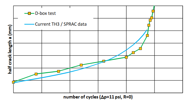
Figure 4: Correlation of computed crack growth in 2024-T3 based on “TH3/SPRAC” da/dN data with test data.
Crack growth results for new alloys
Fig. 5 shows the crack length and pressure vessel opening as a function of the number of ∆p=11-psi cycles (using the available R=.1 da/dN curves) for .045-in skin pocket thickness of:
• 2198-T851;
• 2060-T8E30;
• 2524-T3 Clad.
The pressure vessel opening of mid-bay cracks after 4 intervals (R=0) were used to compare these new thinner materials to that of .050-in 2024-T3 Clad. For the actual comparison the crack length in .050-in 2024-T3 Clad at equal ∆K but R=.1 cycles is added as reference, e.g. 3.1 intervals at equal ∆K but R=.1 result in similar crack length and pressure vessel opening as after 4 intervals at R=0.
Analysis shows that a clearly detectable crack in a .045-in Al-Li 2060-T8E30 skin pocket reaches a similar pressure vessel opening as in the thicker, 050-in 2024-T3 Clad in a considerably longer interval than required. The interval is longer even when the da/dN curve at R=0 is used for 2024 and da/dN curve at the more critical R=.1 (equal ∆K) for 2060 as a conservative approach. This means that the assumption that the R effect is similar for both alloys needs not be used. This favourable result supported the argument for further research and testing of 2060-T8E30.
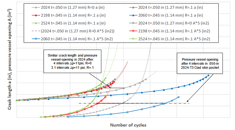
Figure 5: Crack length a and pressure vessel opening A as a function of the number of cycles for .045-in 2198-T851, 2060-T8E30, and 2524-T3
Clad. .050-in 2024-T3 Clad is added as baseline.
Conclusion
This blog discusses the work of Jan Waleson from GKN Fokker: “Analysis of weight reduction of Al-Li high-altitude fuselage”, as presented during the ICAF 2019 conference. 4RealSim was highly involved during the Finite Element simulations in this project.
[1] C 25-20, Pressurization, Ventilation and Oxygen Systems Assessment for Subsonic Flight including High Altitude Operation.

