
24 Nov Finite Element Analysis of Localized Casing Expansion (LCE) technology
4RealSim Finite Element Engineering Services in the offshore industry
4RealSim provides Finite Element engineering services to customers in various industries, and often the work done cannot be disclosed. But occasionally, the work performed is so exceptional that the customer converts the work in a publication and share it with us for promotional use.
Shell submitted a paper: “Restoration of annular zonal isolation using localized casing expansion (LCE) technology: A proof of concept based on laboratory studies and field trial results”. The paper describes the Localized Casing Expansion (LCE) technology and shows that a combination of laboratory experiments, field trials and virtual simulations were combined to investigate the effect on the annular zonal isolation restoration. This blog post will shortly introduce the paper and focus on the value brought by simulation. The full paper can be downloaded from the ScienceDirect webpage. It is published in the “Journal of Petroleum Science and Engineering 197 (2021) 108103”.
Introduction to localized casing expansion
With many oil and gas reservoirs nearing the end of their economic and productive lifetime there is a growing need for effective wellbore plugging and abandonment (P&A) procedures. Achieving robust zonal isolation, i.e. ensuring unwanted fluid migration along the well trajectory is prevented long-term, is a key P&A objective. Zonal isolation must be achieved to prevent seepage into the environment or potable water resources and maintain reservoir containment for future reuse, e.g. in CO2 sequestration or energy storage applications.
Localized casing expansion (LCE) technologies is a possible technique by imposing the radial enlargement over longitudinally limited lengths of casing, e.g. as local indentations or “dents”, bulging out the casing into the surrounding cement. Placement of multiple such dents allows intervals of cement sheath to be axially constrained, enabling effective cement compression and closure of micro-annuli and fractures in the cement over longer length scales.
Shell-developed Local Expander tool
The Shell-developed Local Expander tool imposes the required indentations in a mechanical, fully controlled manner. Figure 1 (courtesy of Shell Global Solutions International B.V.) shows the 7′′ -model Local Expander tool. A shows a photograph of an expander element with sixteen hardened steel fingers and actuated cone. B shows a photograph of the indentation marks visible on the inside of a casing pipe after Local Expander deployment. C shows a schematic cross-section of the complete Local Expander tool.
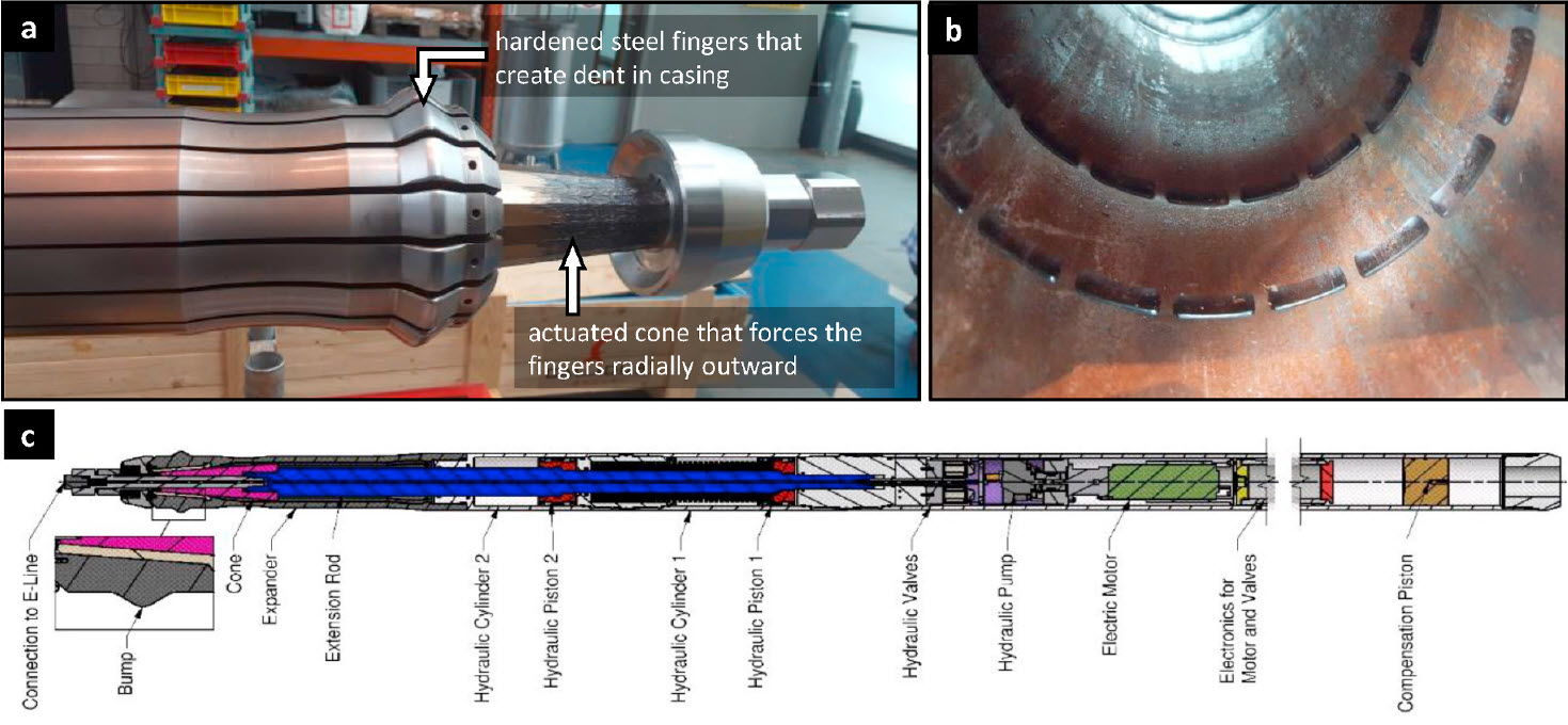
Figure 1: Overview of a 7′′ -model Local Expander tool
A second tool, called the Energetic Expander tool, makes use of tailored shaped explosive charges to achieve similar localized expansions.
Laboratory testing, simulations and field trials
To assess the SCP/SCVF-remediation capabilities of the Local Expander and Energetic Expander tools, a range of sealing performance experiments has been conducted in the laboratory. While the sealing performance test results could evaluate whether the hydraulic barrier function of cemented annuli could be repaired, there was an additional aim to assess the impact of the LCE-induced deformation on the physical integrity of the cement sheath.
LCE technologies impose large stresses and strains on the casing pipe to locally enlarge its diameter. The associated deformations could affect the strength of the casing. Aside from evaluating the primary functionality of LCE technologies in sealing performance tests, specific studies were performed in order to assess the impact of LCE-induced deformations on casing integrity.
Physical testing was conducted to assess how the presence of LCE-induced indentations may impact casing burst strength.
Furthermore, to assess the effectiveness of the Local and Energetic Expander tools, a field-testing programme was implemented in the Canadian oil and gas development region known as Groundbirch, in Northeast British Columbia.
As indicated before, this post will not focus on the physical laboratory or field tests. All details can be found in the original paper. This blog post will describe the virtual casing integrity studies.
Virtual casing integrity studies
LCE technologies impose large stresses and strains on the casing pipe to locally enlarge its diameter. The associated deformations could affect the strength of the casing. Aside from evaluating the primary functionality of LCE technologies in sealing performance tests, specific studies were performed in order to assess the impact of LCE-induced deformations on casing integrity.
Modelling of indentation process and subsequent burst or collapse failure
4RealSim has analyzed for Shell how the presence of LCE-induced dents impacts the burst and collapse strength of a casing. The FEA modelling involved simulation of the entire LCE process, including radial extension and retraction of the Local Expander tool, followed by simulation of burst or collapse loading. Various L80 casings have been simulated, where the pipe weight was varied. These nominal casing dimensions were augmented by representative pipe shape imperfections (0.5% ovality, 10% wall thickness variation as result of eccentricity), uniformly applied along the pipe length. The FEA models considered a semi-pipe configuration (see Figure 2), where the largest principal outer diameter and the eccentricity occur on the symmetry plane. The simulated pipe length was seven times the casing outer diameter, complying with specifications for physical testing.
Figure 2: Finite element model of the Local Expander tool head and a casing pipe. Note the modelled pipe has initial ovality and wall thickness imperfections that are
symmetric about the x-y plane.
The material properties of L80 steel used in the modelling were determined experimentally. The strain-hardening response has been calibrated using an inverse method, thereby incorporating the large strain domain as occurring in the post-necking phase of tensile tests. Linear elastic material properties have been applied to the Local Expander tool. The simulations do not consider the effects of external cement or the surrounding casings and rock formations. Radial extension and retraction of the Local Expander tool have been simulated by incrementing the axial displacement of the actuated cone, while axially fixing the set of expander fingers at the rear end position. The expander fingers are then forced out radially due to the contact definition between these members. For each pipe thickness, two expansion cases have been considered, where the extent of radial displacement was varied. The burst and collapse simulations have been set up to simulate common laboratory testing conditions of respectively capped-end, internal pressure and pure-external pressure loading conditions. These burst and collapse simulations use as starting condition the final geometry and distributions of (plastic) strains, strain-hardening and residual stresses resulting from the simulated expansion and the subsequent retraction of the Local Expander tool. The pressure has been applied incrementally until the maximum bearing capacity of the pipe was reached. The results were compared to reference FEA data, obtained by simulating burst and collapse testing of an undeformed L80 casing (i.e. a dent of 0 mm radial displacement), otherwise imposing the same pipe shape imperfections and burst or collapse loading conditions.
Virtual casing integrity results
Finite element modelling of the casing indentation process
The denting of casing pipe using a Local Expander tool is a complex deformation process, which will here be illustrated for the case of a perfectly cylindrical pipe, where cyclic symmetry (due to finger arrangement) conditions have been utilised. Figure 3 shows two stages during the deformation process in a longitudinal section through the pipe and an expander finger.
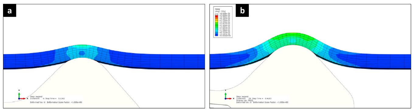
Figure 3: Pipe deformation at various stages of the expansion process (longitudinal section, equivalent plastic strain as field variable), where in a) and b) the expander
finger has been extended by 40% and 60% of its maximum, respectively.
The main straining of the pipe occurred in the hoop (circumferential) direction and was associated with the imposed radial displacements. The hoop straining was largest at the crest of the dent. As the finger was forced outward more, a larger portion of the casing adopted the curvature of the finger crest through bending effects. Bending effects, with opposite sign of the curvature, also occurred in the transition zone between the pipe and the dent. Here, the pipe was not supported by the finger and material got displaced by transfer or internal tension, shear and bending loads. Figure 4 shows a section through the crest of the expander finger during various stages of the expansion process (still under cyclic symmetry conditions).
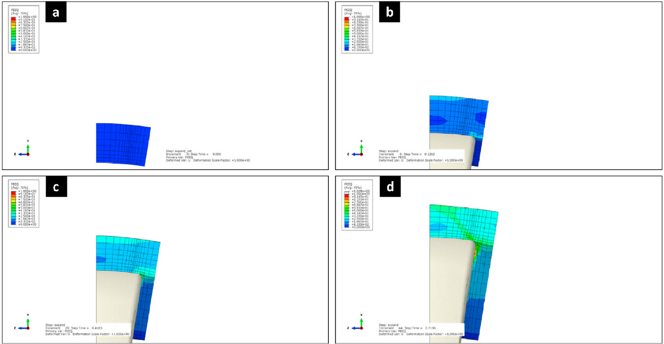
Figure 4: Pipe deformation at various stages of the expansion process (transverse section, equivalent plastic strain as field variable), where a) shows the undeformed
case, and b-d) progressively more extension, up to 80% of the tool maximum.
As radial displacement of the fingers increased, gaps opened-up between the neighboring fingers, causing an increasing portion of the pipe inner circumference to lose contact with the fingers. Consequently, the degree of plastic straining became non-uniform around the pipe circumference. The degree of wall thinning became somewhat less at the unsupported sections. A zone of increased plastic straining in the pipe occurred along the edge of the fingers. This zone is associated with plastic relief of (contact) stress-concentrations. Figure 5 shows the final distributions of equivalent plastic strain and the residual von-Mises stress after the Local Expander tool has been retracted.
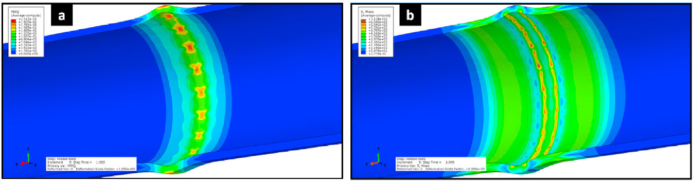
Figure 5: Non-uniform plastic strains (a) and residual von-Mises stresses (b) due to initial wall thickness variations of the pipe and due to the finger configuration of
the Local Expander tool. The simulation shown involves a L80 pipe that has been dented by up to 12.7 mm of radial
displacement.
In this simulation, an L80 casing pipe with initial ovality and wall thickness imperfections incorporated, was dented to 12.7 mm radial displacement. In addition to the expander finger induced cyclic variations, the overall strain level increases from bottom to top. This is attributed to the applied non-uniform wall thickness in the initial pipe geometry, which further developed during the expansion process. Apart from some ‘finger induced hot-spots’ the highest overall residual stresses occur in the transition zone from the nominally straight pipe to the dent.
Finite element modelling of casing collapse failure
The collapse strength of pipes refers to the load bearing capacity of the pipes under predominant external pressure loading conditions. It is governed by the stability of the nominally-round pipe shape. Figure 6 shows the calculated responses of L80 casing pipes to collapse loading, plotting pipe ovality versus applied external pressure, for undented pipe as well as dented pipes with 12.7 and 19.1 mm applied radial displacement.
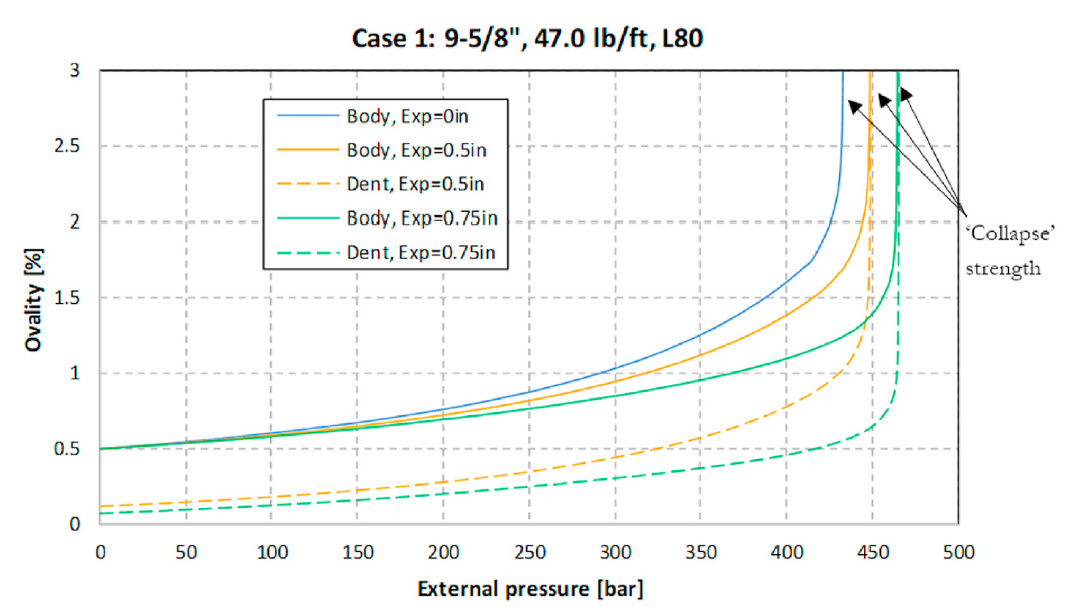
Figure 6: Evolution of the ovality at the pipe body and at the crest of the dent versus the applied external pressure for an L80 casing pipe and for different degrees of applied denting. The pipe has initial imperfections of 0.5% ovality and 10% local wall thickness reduction.
Response curves for dented pipes are given for both the main pipe body (represented by a position half-way between the dent and pipe end) and for the crest of the dent. Note the denting process reduced the initial pipe ovality locally around the dent. Moreover, upon collapse loading, ovality in the pipe body developed at a slower pace with pressure in the dented pipes, compared to the undented reference pipe. Further note that the ultimate pressure bearing capacity also increased when dents were applied (see Figure 6). Qualitatively the same effects were observed for the thinner and thicker pipe cases considered in the simulations. Given these results, the dents seem to serve effectively as local stiffener against collapse failure. Note, however, that this will practically no longer be effective for larger pipe lengths. The conclusion from these analyses is therefore that collapse strength of dented pipes remains to be governed by the pipe body, with dents possibly acting as local stiffeners.
Finite element modelling of casing burst failure
The burst strength of a pipe refers to its load bearing capacity under predominant internal pressure conditions. One of the design objectives is to prevent release of fluids contained inside the pipe to the environment. This involves the occurrence of yielding, plasticity and finally fracture of the pipe. Figure 7 shows a capped-end example of the calculated changes in average diameter and minimum wall thickness that occur during internal pressure loading.
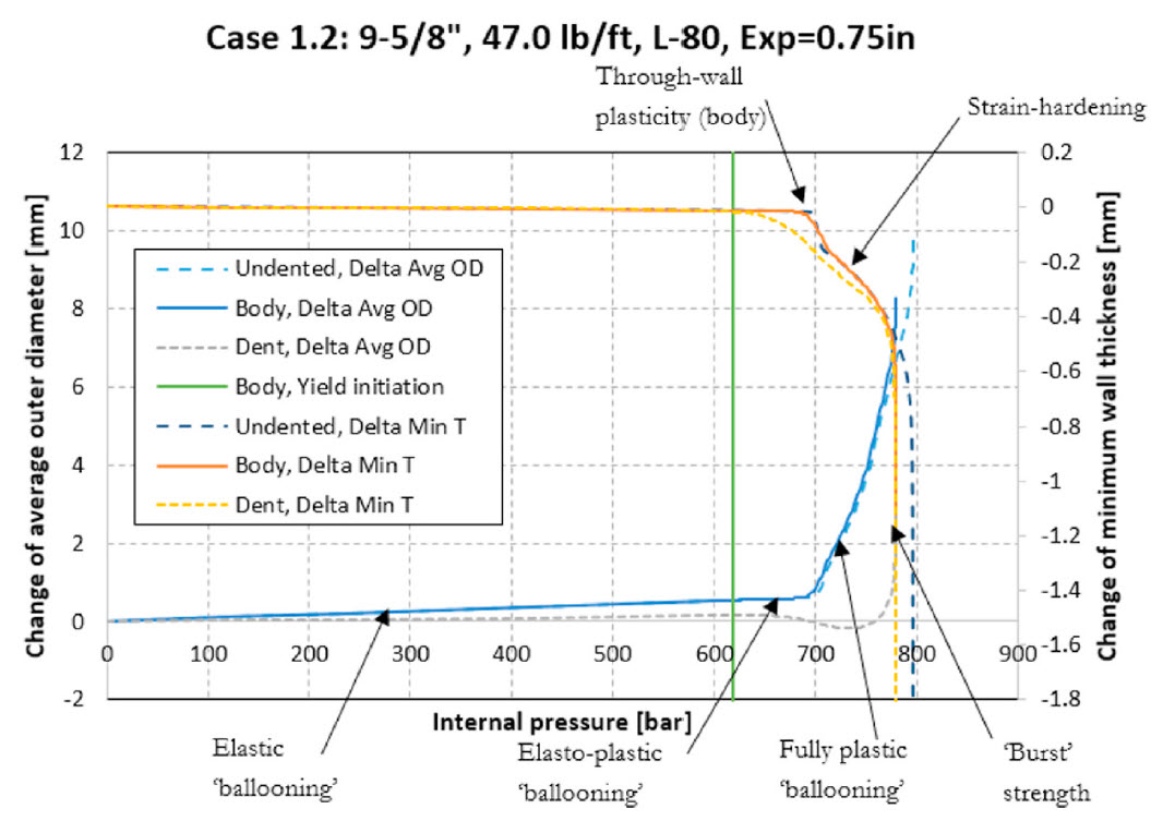
Figure 7: Typical response of the changes of the average outer diameter (denoted Avg OD) and the minimum wall thickness (denoted Min T) versus internal pressure.
The response curves are given for the pipe body and dent crest locations.
The results shown are for a L80 casing that has been dented to 19.1 mm radial expansion. Response curves are given for the pipe body, at a position halfway between the dent and the pipe end, and for the crest of the dent (note the latter curves exclude dimensional changes incurred during the denting itself). The response of an undented reference pipe is also shown. The diameter and wall thickness responses for the body of the dented and undented pipe were practically the same. The outer diameter increased (‘ballooned’) and wall thickness decreased under the applied internal pressure. The responses for the pipe body were linear up to the yield initiation pressure (here 618 bar, Figure 7), where yielding initiated at the inside of the pipe body. In conventional casing design practice, this pressure level or loading condition is used as the design limit. This internal pressure level can also be accurately predicted using industry accepted triaxial design equations, when the minimum wall thickness of the pipe is accounted for. These conventional design equations assume the pipes have negligible residual stresses from the manufacturing process. It should be noted, however, that the pipe has significant capability to take additional loads beyond this initial yielding (Figure 7). While the general design philosophy is to not exceed the yield limits, it is useful to discuss the post-yielding responses observed, as this provides insight in the actual safety margins with respect to events of (catastrophic) pipe failure and consequently losing the ability to contain pressure and fluids. It is of key importance to know whether these limits have been affected by the LCE-process. After exceeding the yield limit, deformation of the casing became elastoplastic. With increasing internal pressure, the plastic zone, initiated at the inner surface of the pipe wall, grew at the expense of the zone in the pipe wall that still deformed elastically. However, (hoop) strains at the pipe outside remained elastic and thus small. Consequently, radial displacements, wall thickness reductions and pipe diameter enlargements also remained relatively small during this phase. Once plasticity occurred over the entire wall thickness (here 700 bar, Figure 7), increasing rates of plastic ballooning and wall thinning occurred in the pipe body. Initially, strain-hardening of the material required progressively higher pressures for plastic deformation to continue. This effect levelled out, however, due to the opposing effects of material strain-hardening and continued wall thickness reduction. The ultimate pressure bearing capacity was reached at 778 and 796 bar for the dented and undented pipe, respectively (Figure 7), as the weakening effect of pipe wall thickness reduction becomes dominant over strain-hardening effects. At this point, a necking zone occurred along the longitudinal direction, with accelerated plastic straining and stress-triaxiality development, with fracture being imminent. The LCE denting process created large residual stresses in the pipe around the transition zone between the dent and the pipe body (Figure 7). During burst loading, the presence of these residual stresses caused plasticity to re-initiate already at relatively low levels of applied internal pressure. These plasticity effects do not constitute a significant reduction of the load bearing capacity of the pipe as a whole, as the residual stress state is self-contained, i.e. does not have some net-resultant force. Therefore, these plasticity effects only constitute a plastic relief of the residual stresses. Figure 7 also shows that through-wall plasticity initiated at a lower pressure around the dent compared to the main pipe body. This weakening was related to an already reduced local wall thickness (note the material also already had undergone strain-hardening) and a different loading situation (e.g. also tension and bending effects). Therefore, on the one hand, the dent can be considered as a local weak spot. On the other hand, the body and dent responses (for a dented pipe case) both tended to the same limit pressure of 778 bar (Figure 7). Hence, at a certain stage, local wall thinning around the dent can only develop further, or become unstable, if through-wall plasticity is also occurring in the overall pipe body. These results can be explained by considering the axial extent of the thickness reductions at the (crestal) position of the dents. Notably, the (tangential) displacement field should also be continuous in the axial direction of the pipe. Large gradients therein would involve large tangential and axial shear strains and associated stresses in the transition zone between the dent and main pipe body. This is energetically unfavourable and, therefore, the pipe body material adjacent to the dent effectively gives support to resist localized neck development at the dented zone. Still, the adjacent pipe body material does not act as a complete arrestor of necking at the dent. The dented zone remains to act as weakening, but the effect on the ultimate pressure bearing capacity (by induction of unstable necking) is very limited. Qualitatively the same results were obtained for the other cases considered in this study involving thicker and thinner pipes and/or with the expansion of only 12.7 mm. The reduction of the ultimate pressure bearing capacity for the L80 casings considered in this study was within 10 and 30 bar when expanded to 12.1 mm and 19.1 mm radial enlargement, respectively. Overall, these are relatively small effects.
Finite Element conclusion
Finite element modelling of the LCE process and subsequent loading of the dented casing pipe to burst or collapse failure demonstrated indentation does not significantly reduce the pipe’s collapse strength, while the impact on burst strength is shown to become relevant only in cases of extreme unanticipated overloading. These findings are supported by laboratory testing.
4RealSim Finite Element Engineering Services in the offshore industry
4RealSim provides Finite Element engineering services to customers in various industries. Contact us if you would like to discuss your cases.

