19 May Hydrogen Embrittlement
Hydrogen Embrittlement – A serious challenge for the industry
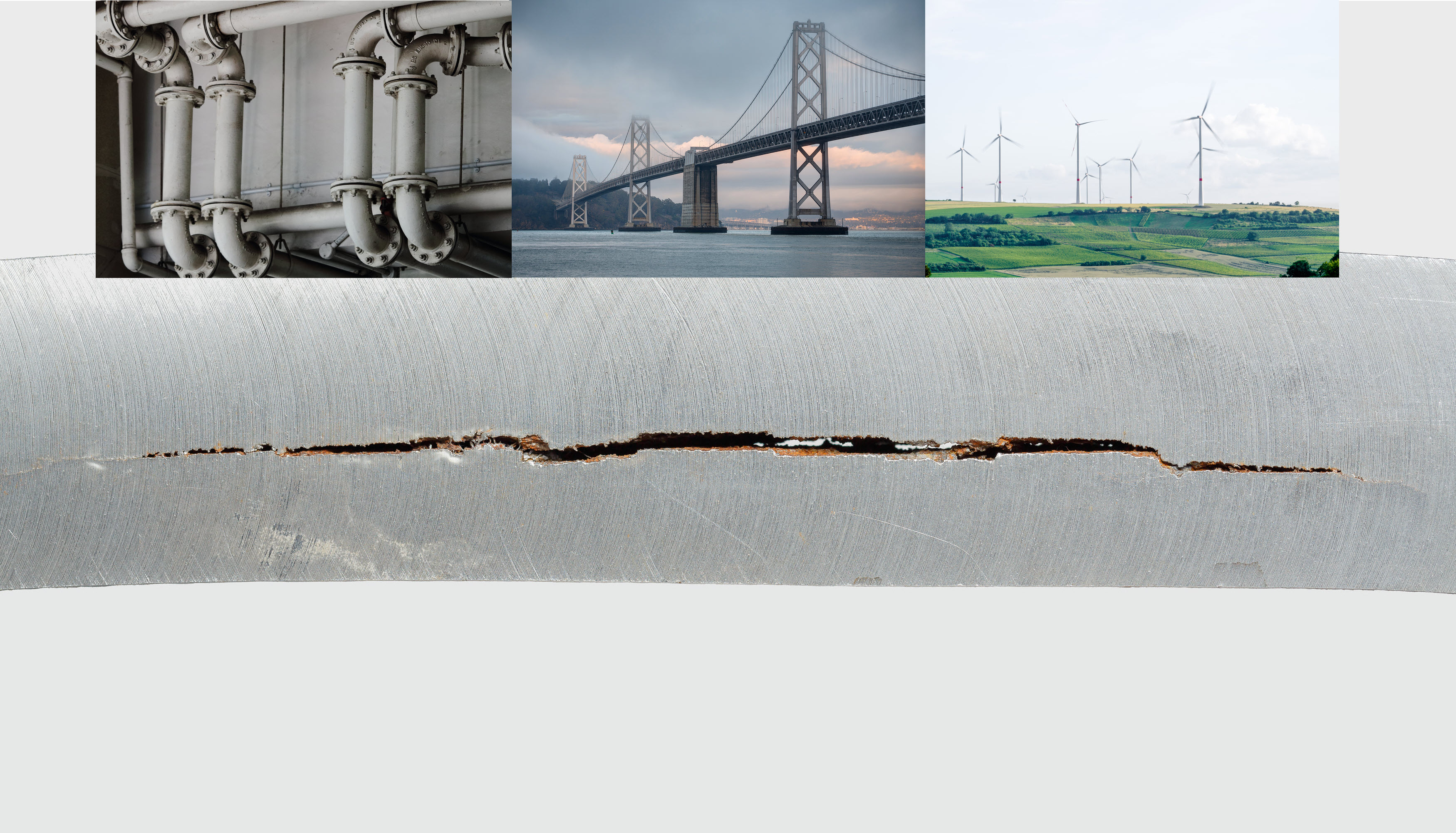
Hydrogen embrittlement (also called hydrogen assisted cracking or hydrogen-induced cracking) describes the embrittling of metal after being exposed to hydrogen. Due to hydrogen embrittlement, structures can suffer from a loss of ductility, strength and/or toughness. This phenomenon can pose a risk to the sustainability of oil and gas structures, gearboxes and anchors of offshore wind turbines or steel architectural constructions. Although it is a serious treat for steel structures, hydrogen embrittlement remains a complex process that is not completely understood because of the variety and complexity of mechanisms. Numerical methods can help investigating different theories and compare obtained results with experimental data.
4RealSim, partner to tackle Hydrogen Embrittlement
4RealSim is a Finite Element Analysis consultancy company active in the Oil & Gas, Aerospace, Automotive, Construction and Energy industry. In the past years 4RealSim has been investigating hydrogen embrittlement and implementing numerical solutions, in order to help our customers understand their cases of hydrogen embrittlement.
Contact info@4realsim.com to discuss your hydrogen embrittlement case.
Hydrogen Embrittlement cases
Oakland Bay Bridge
One known case of hydrogen embrittlement is the Oakland Bay Bridge. In 2013, 6 months prior to opening, the east span of this bridge failed during testing. Catastrophic failures occurred in a high percentage of the shear bolts in the span, after only two weeks of service. The failure is attributed to embrittlement, most likely originating from the harsh environment. The costs are estimated to be more than 25.000.000 $.

New eastern span of Oakland Bay Bridge – Picture by Mario Roberto Durán Ortiz
122 Leadenhall street
122 Leadenhall street, also known as the “Cheesegrater”, suffered from hydrogen embrittlement in numerous steel bolts, with three bolts failing in 2014 and 2015. But not only the construction industry is facing hydrogen embrittlement. This phenomenon is also a problem for the oil and gas, wind energy and various other industries.
Background information on Hydrogen Embrittlement
When metal is exposed to hydrogen, it can face a loss of ductility, strength and/or toughness. To characterize this behavior, hydrogen embrittlement has been investigated intensely over the past decades, which led to various competing models and theories. Below subset of these theories are summarized:
- HELP: hydrogen enhanced localized plasticity
- HID: hydrogen induced decohesion
- HIPT: hydrogen induced phase transformation
With the help of numerical methods companies can assess these theories and compare the obtained results with experimental data obtained in the field.
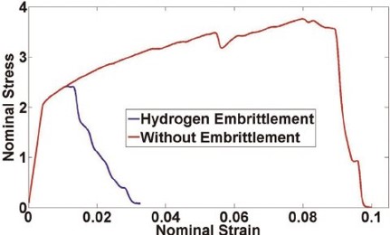
Influence of Hydrogen Embrittlement on material properties
The main problem is that hydrogen can easily diffuse through the metal structure and from a macroscopic level hydrogen can be found at various locations.
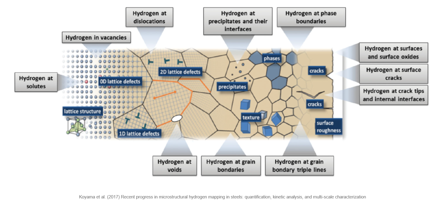
Recent progress in microstructural hydrogen mapping in steels – Picture by Koyama et al.
Coupled stress-hydrogen diffusion
In many commercial FEM-packages the standard diffusion process is implemented and can be solved with a dedicated process. But the coupled stress-hydrogen diffusion process is not readily available and needs to be programmed and implemented.
The coupled diffusion process discussed here is based on the HELP model, which requires the separate treatment of the hydrogen concentration at the lattice site (coefficient CL ) and at the trap-site (coefficient CX ), which is related to the development of local dislocations. The total hydrogen concentration (CT) is the sum of lattice-site and trap-site concentration.
Suitable numerical approaches were developed by Krom (1999), Oh and Kim (2009), Barrera (2016), and others, which used the law of mass conversation and divergence theorem to derive the necessary numerical solutions that need to be implemented into the FEM code:
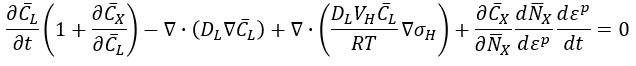
Final divergence theorem
Coupled stress-hydrogen diffusion implementation in Abaqus
A very nice analogy is seen when comparing the mass diffusion equations with the heat equations from a high level overview (see picture below). This means that the heat transfer framework can be “manupilated” to cover the mass diffusion theory. In such way a fully coupled stress-hydrogen diffusion solution can be implemented into Abaqus.
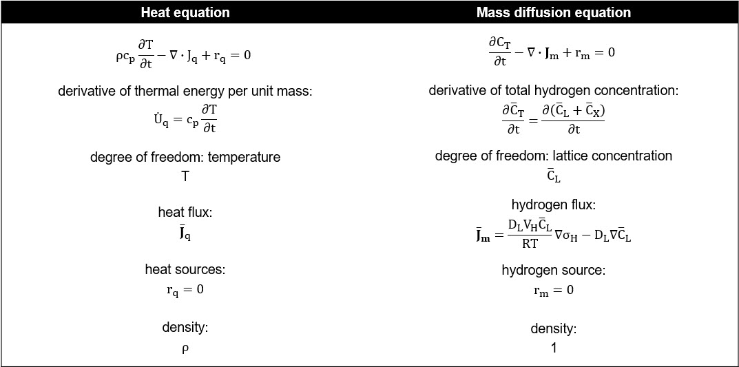
Heat equations versus mass diffusion equations
In a coupled solution the stress and boundary conditions influence the hydrogen concentration, while the hydrogen concentration influences the material behavior, visa-versa.
The diffusion equation itself is solved with the user-subroutine UMATHT.
Another challenge was to calculate the hydrostatic stress gradients, which are calculated in the UMATHT routine via the shape function derivatives.
Furthermore the formula to calculate the yield stress as a function of the plastic strain is extended to take the hydrogen concentration via the UHARD user subroutine into account.
Validation of the coupled stress-hydrogen diffusion implementation
A case from literature is taken to validate the coupled stress-hydrogen diffusion implementation. The case evaluates the hydrogen transport near a blunting crack tip.
The case (see picture below) represents a 2D plate with a crack and deformation is applied to have a mode-I crack and a stress intensity factor of 89.2 MPa√m.
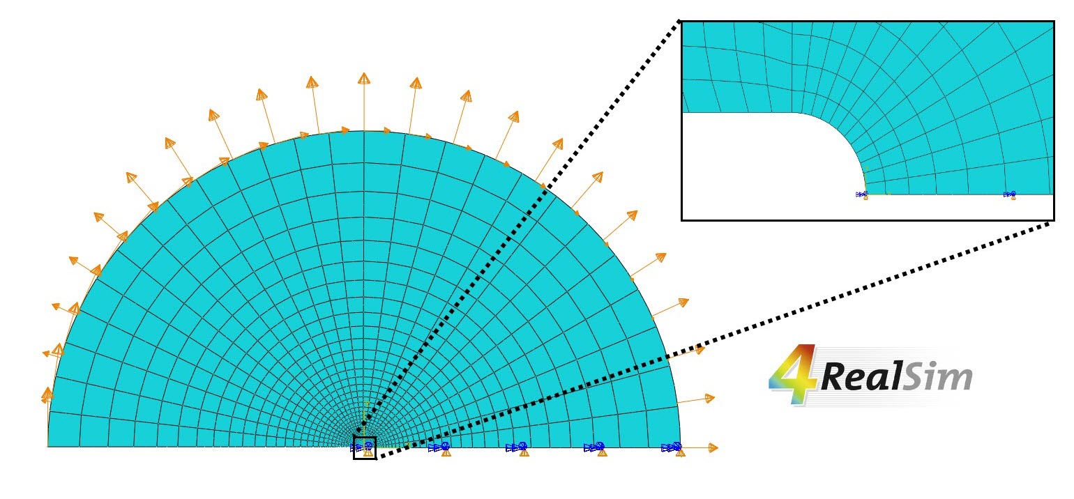
Geometry and loads/BC of sample case
The hydrogen development over time is assessed when there is a different loading rate: extremely fast at 1.3 sec and extremely slow at 1.3E+6 sec.
Furthermore there is no hydrogen flux to the exterior surfaces and there is a uniform initial hydrogen concentration inside the component.
The coupled stress-hydrogen diffusion FEA results
The results obtained with the implemented solution are very similar compared to the results available in literature. In the following section more details about these results are given.
The hydrogen concentration at the lattice sites is shown on the left side of the video below, while the hydrogen concentration at the trap sites is shown on the right side. Also note that the legend of the hydrogen concentration at the trap sites is 100 times higher than the hydrogen concentration at the lattice sites.
For the fast case (see video below), the hydrogen concentration at the lattice sites is increasing (the red zone) for a short period at the beginning of the simulation, as the hydrostatic stress is increasing. It is attracting all hydrogen of the surrounding and then it is disappearing. All hydrogen at the lattice sites is gone.
The hydrogen at the trap sites is dependent on the development of plastic deformation. The plastic deformation is not increasing immediately at the beginning, but after a while it does increase and thus also the hydrogen at the trap sites is increasing. So after a while the hydrogen of the lattice site moves to the trap sites.
For the slow case (see video below), a steady growth of the hydrogen at the lattice and trap sites is shown, near the tip of the blunted crack.
The simulation results clearly shows the influence of the loading rate on the hydrogen concentration at the lattice and trap sites. This is also seen in literature.
Crack propagation
In the second phase the crack propagation is included in the simulation. The crack and future crack path is predefined by means of a cohesive zone model. The cohesive behavior is characterized by cohesive stiffness, cohesive strength and cohesive fracture energy.
Crack propagation implementation
The cohesive strength is dependent on the hydrogen concentration at the surfaces. The cohesive fracture energy is considered independent of the hydrogen concentration, but if needed, dependency could be included.
Crack propagation study case
Some cases from literature are taken to verify the implementation of the crack propagation. In this blog the case of the double-cantilever beam (DCB), which is a standard specimen for material testing (NACE DCB), is described. The DCB is modeled as a 2D-model, with a predefined crack at the mid-line surface. The crack is pre-cracked.

Geometry of double-cantilever beam
Loads
In a first step the free ends are vertically pulled and in a second step a hydrogen loading is applied at the exterior boundary surface of the DCB.
Crack propagation FEA results
When the free ends of the DCB are vertically pulled (first step), one can see in the video below that the Mises and hydrostatic stress close to the crack tip are slowly increasing.
In the video below the obtained Mises and hydrostatic stress patterns are shown when the hydrogen loading is released to the exterior boundary surface of the DCB (step 2). During this step, the hydrogen is released at t0 and afterwards the hydrogen is being ramped up and kept constant. The hydrogen approaches the crack tip, degrades the material and thus reduces the cohesive strength. The reduction in cohesive strength causes the opening of the crack.
At a certain moment, an equilibrium is reached between the external mechanical loading and the resulting stress concentration at the propagated crack tip and the degraded material properties. Once these are in balance (this means the cohesive strength equals the critical loading), there is a self-arresting crack.
The video below shows the hydrogen concentration at the lattice sites (top) and the cohesive strength ratio. The hydrogen concentration is focusing on the crack tip. The cohesive strength ratio (value 1 at the beginning of the step) is deteriorating at the crack tip, till the crack arrest happens.
The video below shows the same results but zooming closer to the crack tip.
This post does not describe the results of the parameter investigations (mesh size, fracture strength, fracture energy, fracture viscous damping, …), but these results can be discussed on demand.
Conclusion: Hydrogen Embrittlement FEA solutions
To conclude, 4RealSim has implemented and verified a fully coupled stress-hydrogen diffusion mechanism. This solution can be used to evaluate the relevance of hydrogen embrittlement at different levels.
A first possibility is to use this solution to assess the macroscopic impact on the yield behavior, in order to evaluate the relevance of hydrogen diffusion / concentration in the structure .
Another possibility is to use this solution to assess the macroscopic impact on material degradation / damage, in order to evaluate possible failure loads by accounting for local material damage as a result of hydrogen embrittlement.
A third possibility is to use this solution to assess the microscopic impact on crack growth / development. This allows the user to
How can 4RealSim help with Hydrogen Embrittlement?
4RealSim has the expertise and knowledge to tackle hydrogen embrittlement challenges. 4RealSim can develop a tailored subroutine, a tailored simulation process or 4RealSim can work independently to investigate the hydrogen related problem.
Contact info@4realsim.com to discuss your hydrogen embrittlement case.

