
Predicting crack paths without manual remeshing
Updated: Jun 22

Fatigue crack growth simulations are traditionally iterative and labor intensive. Each increment in crack length requires geometry updates, remeshing, state mapping, and manual intervention. This procedure slows down development, especially when evaluating multiple geometrical variations or load cases.
For linear elastic fracture mechanics problems under cyclic loading, engineers need:
Accurate stress intensity factor evaluation
Robust crack path prediction
Automated mesh update near the crack front
Minimal analyst intervention
The 2026 Abaqus Standard capability for fatigue crack growth with tetrahedral element based adaptive remeshing addresses exactly this bottleneck.
Combining Paris law with contour integral fracture mechanics
The method integrates classical fracture mechanics with automatic remeshing.
Crack growth rate is computed using the Paris Law:
[ da/dN = C(\ΔK)^m ]
Where ΔK is obtained using the contour integral method at the crack front.
After each crack increment:
The crack front is updated
A new tetrahedral mesh is automatically generated
The mesh conforms to the updated crack geometry
The next fatigue increment is solved.
Because the method is limited to linear elastic fatigue crack growth, no state mapping is required between increments. This significantly simplifies the workflow.
Modified compact tension benchmark with curved crack path
To demonstrate the capability, a modified compact tension specimen based on Miranda et al. (2003) is analyzed. An additional hole is introduced to curve the crack propagation path.

The geometry of the described specimen includes:
A standard compact tension specimen with a primary crack notch
An additional hole of 7 mm diameter placed to the side of the crack path
Cyclic tensile loading applied at stress ratio R = 0.1
Two configurations, CT1 and CT2, with the hole positioned at slightly different vertical distances from the notch root
The relative hole position determines whether the crack deflects away from the hole or propagates toward it.
CT1 case: Crack deflection away from the hole
In the CT1 configuration, the crack initially propagates toward the hole. As it approaches, the stress intensity redistribution causes the crack to deflect away.

The numerical prediction aligns closely with the experimental trajectory.
To better visualize the crack evolution:

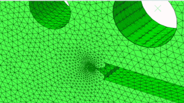
CT2 case: Crack attraction and penetration into the hole
In the CT2 configuration, the hole position causes a different stress redistribution. The crack propagates toward the hole and ultimately merges into it.

The simulation reproduces the experimentally observed attraction effect.
For visualization:


How automated crack growth improves engineering workflows
This capability eliminates the need for:
Manual crack front advancement
Rebuilding meshes between increments
Custom scripting for geometry updates
Repeated analyst driven preprocessing
It enables:
Fully automated fatigue crack growth studies
Rapid evaluation of geometric variations
Early stage durability validation
More reliable crack path prediction in complex geometries
For industries such as aerospace, offshore, heavy machinery, and energy, this reduces simulation turnaround time and increases robustness of fracture assessment workflows.
Implementing adaptive fatigue crack growth in practice
To use this capability effectively:
Define a linear elastic material model
Use contour integral evaluation for stress intensity factors
Activate tetrahedral adaptive remeshing
Define fatigue parameters via Paris law
Validate against known benchmark geometries
Correct setup of fracture criteria and remeshing controls is essential for stable convergence.
Accelerating fracture simulations with the right setup
Adaptive fatigue crack growth requires more than activating a feature. It requires correct fracture setup, mesh control strategy, validation methodology, and alignment with your durability process.
4RealSim supplies SIMULIA Abaqus licenses and supports companies in implementing automated fracture workflows, from initial benchmark replication to integration into production durability programs.
If you are evaluating Abaqus for fatigue crack growth or want to replace manual crack propagation procedures with a robust automated workflow, contact 4RealSim at marketing@4realsim.com. or fill in the contact form to discuss software acquisition and technical implementation support.
References
Miranda, A., M. Meggiolaro, J. Castro, L. Martha, and T. Bittencourt, “Fatigue Life and Crack Path Predictions in Generic 2D Structural Components,” Engineering Fracture Mechanics, vol. 70, 2003.
This article is based on publicly available information from Dassault Systèmes SIMULIA.

Comments