17 Jan Obtain accurate results with shell models under torsional load – drill DOF stiffness
4RealSim Engineering Services to assist customers with their Finite Element challenges
4RealSim provides Finite Element engineering services to customers in various industries. In 2021, the Ghent University contacted us to work together to understand the mismatch between shell and solid models when subjected under torsional loading.
Ghent University (with 4RealSim) submitted a paper how more accurate results can be obtained with shell models: “Finite element analysis of wind turbine blades subjected to torsional loads: Shell vs solid elements”. The paper describes how the stiffness difference between the offset shell and solid models was reduced from 35% to 5%. This blog post will shortly summarize the paper. The full paper can be downloaded from the ScienceDirect webpage. It is published in the “Composite Structures, Volume 280, 15 January 2022, 114905”.
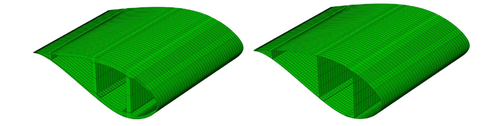
Wind turbine blade under torsional loads
In this work an analysis of the behaviour of a wind turbine blade under torsional loads was performed. Based on these results, it was concluded that the baseline OML shell models did not accurately capture the behaviour of the blade when a torsional load was applied. The torsional stiffness of the OML shell models was observed to be 30% lower than that of the solid model. Additionally, it was concluded that although using shell models with no offset improved the results. Nevertheless, these models still had a more compliant behaviour when compared to the models with solid elements.
Cylinder subjected to torsional loads
To better understand the discrepancies between using models with solid elements and models with shell elements, a cylinder tube was analysed under torsional loads, due to the availability of an analytical solution to this problem. This problem allowed the identification of an issue with the stiffness of the drilling DOF (rotation perpendicular to the shell’s plane) for the shells defined with an offset surface, i.e., shells where the nodal plane does not coincide with their mid plane. Shell element formulations with 5 and 6 DOFs exist, 6 DOF shell elements are required to enforce compatibility for 3D shell models at for example intersections and foldlines. A singularity exists though for these 6 DOF shell elements where the surface is smooth, therefore an artificial stiffness is added to the in-plane rotational. From the analyses that were performed, it was concluded that the standard drilling stiffness is in some cases too low, specially in offset shells, leading to artificial deformation modes (and energy) and inaccurate results. In Abaqus, the drill stiffness can be increased by a user defined multiplicative factor, which was seen to drastically improve the results in models with layered orthotropic materials.
Wind turbine blade models with increased drill stiffness
Based on the findings from the cylinder models, blade models with increased drill stiffness were analysed. From these results it was concluded that this leads to a significant improvement in results for the OML shell based models traditionally used to analyse these components. Furthermore, it was seen that the offset shell models with increased drill stiffness, had similar behaviour to the models with standard shells (nodal plane coincident with the middle plane). Nevertheless, these models still presented a stiffness around 10% lower that predicted by the solid models.
Detailed analysis of the geometry
To further analyse the differences between the two modelling strategies (shell vs solid), a detailed analysis of their geometry was conducted. From this analysis it was possible to verify that, due to the meshing requirements of the software used to generate the models, the solid models had higher thickness in some regions of the blade, thus more material, than the shell models. Based on this evidence, a new solid model was created including thickness transition zones to improve its fidelity. This lead to a 5% reduction of the stiffness of the solid model. Comparing the improved solid model and the OML shell model with increased drill stiffness, it is concluded that the shell model predicts a stiffness that is 5% lower than the one predicted in the solid model.
Accuracy improvement of wind turbine blades modelled with shell elements
The results presented in this work highlight the challenges in modelling wind turbine blades under torsional loads and the need for high fidelity models to capture its behaviour. A significant improvement in the results of OML based shell models for wind turbine blades under torsional loads was achieved by increasing the drill stiffness of the shell elements, reducing the different between the OML shell model and the solid model from 35% to 5%. Nevertheless, the higher fidelity solid models were seen to predict a 5% higher stiffness, which can be significant when designing a wind turbine blade, not only under static loads but also with respect to its dynamic behaviour.
More information
Dassault Systèmes Simulia Drill DOF Stiffness for simulia Abaqus shell elements QA00000007934. Tech. rep., Simulia Knowledge Base; 2021, URL, https://kb.dsxclient.3ds.com/mashup-ui/page/document?q=docid:QA00000007934.

