05 Sep Mesh quality checks tools Abaqus
The importance of FE mesh quality and mesh quality checks tools in Abaqus/CAE
In this blog post, we will discuss why the FE mesh quality is of crucial importance and what measures and tools are available in Abaqus to check the quality of your FE mesh.
Why is the quality of a FE mesh really important?
Unexperienced users with little training might generate meshes able to pass the FE processor’s test and blindly trust the accuracy of the FE solution, without prior checking their mesh quality. A low-quality mesh is likely to lower the accuracy of your FEM results or, even worse, provide totally inaccurate results. It is therefore important to make sure our model has a good quality FE mesh.
Which is the main cause of poor mesh quality?
When meshing highly irregular and complex geometries, the finite element shape must deviate from its ideal shape. If we consider 2D finite elements, the ideal shape of a triangular element is an equilateral triangle, whereas for a quadrilateral element it is a square. In 3D problems, the ideal shape for a tetrahedron element is a regular tetrahedron, for a hexahedron element it is a cube and so on. These are shown in the figure below.
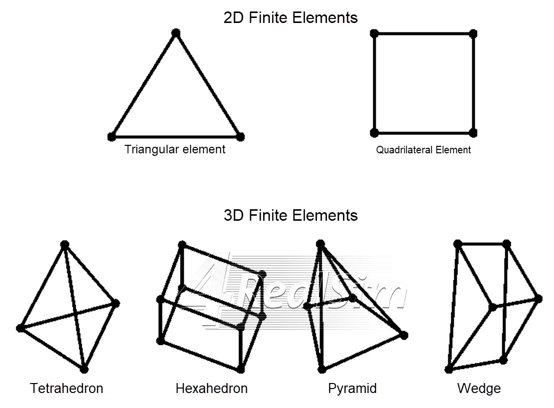
Ideal shapes for 2D and 3D finite elements
Every finite element is designed to work properly within certain ranges of element distortion before it degenerates, i.e. before two or more nodes fall on the same coordinate. The amount of distortion allowed before degeneration is mainly dependent on the element type and numerical procedure used within the element formulation.
Is refining the FE mesh an easy solution to improve mesh quality?
It is common knowledge among FE analysts that the easiest way to improve the accuracy of the solution is by increasing the FE mesh density, provided no singularities exists in your mesh. This also happens to be a way of controlling the quality of the mesh. In general, smaller elements more likely to deviate less from the ideal shape, but one should be aware that there might be instances in which quality requirements are violated even when mesh density is increased. Furthermore, increased FE mesh density will result in longer analysis run times and require more memory on your machine. While we might be willing to accept this for a “one time run”, this becomes highly undesirable for multiple iteration runs. As a general rule of thumb, we would like the quality of our mesh to be just “good enough”. In simple words that means working with a mesh able to produce results with a satisfying degree of accuracy for the problem of interest and characterized by an acceptable run time. From a practical point of view, the element size of such mesh should derive from mesh convergence studies and the mesh should pass the checks for quality requirements.
What measures can we use to quantify element distortion and check our FE mesh quality?
There are different measures one could use to quantify element distortion and avoid element degeneration. Element distortions are measured with respect to the element ideal shape. Abaqus is equipped with in-built tools to check FE mesh quality, using element shape and size metrics. These checks are available in the Mesh Module of A/CAE (Mesh Module -> Mesh -> Verify…).
When verifying a mesh, the user can toggle on the Errors and Warnings on the Analysis Checks tab to display the results separately, as shown in the figure below. Doing so Abaqus will highlight the elements with a poor shape (warnings) or degenerated elements (errors). It is worth to note that elements issuing a warning message can pass the FE processor’s test, whereas elements issuing an error message are not able to pass the FE processor’s test.
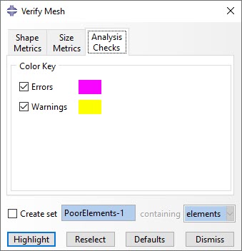
Analysis checks and set controls in the Verify Mesh dialog box
Different types of shape metrics are used in Abaqus to check on element distortion:
Face Corner Angle
This measure is used to check how much the element deviates from its ideal shape (skewness), by calculating element face corner angles. Through the Verify Mesh Abaqus tool, the user can set criteria on the Shape Metrics tab so that Abaqus will highlight elements with face corner angles smaller or larger than certain values. Skewness and face corner angle criteria are shown in the figure below.

Skewness for 2D elements and corresponding mesh quality check
Aspect ratio
This factor refers to the ratio between largest and smallest characteristic dimension of an element. Large aspect ratios are associated with increased inaccuracy of the FE representation and can have a detrimental effect on convergence of the FE solution. The ideal aspect ratio of 1 cannot be maintained for complex geometries. As a general rule of thumb, small aspect ratios should be maintained in critical areas of the domain to retain accuracy of the FE solution. Through the Verify Mesh Abaqus tool, the user can set a criterion to highlight elements with an aspect ratio larger than a certain value, as shown in the figure below. By default, Abaqus will issue a warning for elements with an aspect ratio larger than 10.
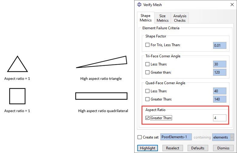
Aspect ratio for 2D elements and corresponding mesh quality check
Alternatively, the user can make use of the Size Metrics tab on the Verify Mesh dialog box to highlight elements that do not meet one or more of the following criteria:
Geometric deviation factor
This factor is a measure of how much an element edge deviates from the original geometry. This value is calculated in Abaqus/CAE by dividing the maximum gap between the element edge and its parent geometric face or edge by the length of the element edge, as illustrated in the figure below.
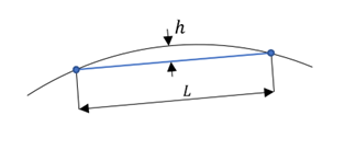
Geometric deviation factor visualized
Short edge
This criterion is used to highlight elements with edges shorter than a specific value.
Long edge
This criterion is used to highlight elements with edges longer than a specific value.
Stable time increment
Stable time increment is a meaningful parameter only when using the Abaqus/Explicit solver. To calculate the element based stable time increment, it is required to define a suitable material and assign the corresponding section to the meshed region to be verified. Using this criterion, Abaqus will highlight elements with a calculated stable time increment less than the specified value.
The Size Metrics tab within the Verify Mesh dialog box is shown in the figure below.
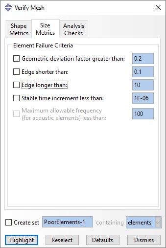
Size metrics tab in the Verify Mesh Abaqus tool

